Bijur Delimon PVB Mobile Divider Valve
Mobile, Series Progressive Systems
GENERAL
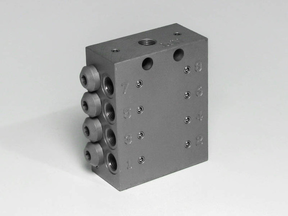
The PVB Divider Valve accurately meters and dispenses lubricant to as many as 20 outlet lines at operating pressures up to 3600 psi. Output volumes are fixed at 0.17cc (0.01 cu. in.) per cycle but can be combined with other outlets by using appropriate fittings for larger outputs. Valves are available with cycle indicator pins to provide visual confirmation of system operation. In addition the cycle pin can be fitted with a switch to provide electrical feedback to a system controller.
OPERATION
Operational sequence of a PVB Divider Valve is defined as “progressive,” meaning that each valve segment completes its piston stroke, discharging a positive volume of lubricant to the point it serves before the following valve segment operates. As long as lubricant is supplied under pressure to the inlet of the divider valve, these segments will continue to operate in a progressive manner. The divider valves will always follow a constant discharge pattern. When lubricant flow ceases, the pistons will stop. Whenever flow resumes, the pistons will start again at the same point in the discharge cycle.
FEATURES
- Flexible design allows for on-site configurations
- Valves available in sizes ranging from 6 to 20 outlets
- Positive displacement discharge
- One switch monitors complete system
- Valves are corrosion resistant
TECHNICAL DATA
| Lubricant | Grease | NLGI grade 000-2 |
| Oil | ISO VG 68 to 1500 at working temp. | |
| Synthetics | Contact factory prior to use | |
| Discharge/Cycle/Outlet | 0.17cc (0.01 cu. in.) | |
| Minimum Pressure | 145 psi (10 bar) | |
| Maximum Pressure | Without indicator pin | 4350 psi (300 bar) |
| With indicator pin | 2300 psi (160 bar) | |
| Maximum Differential Pressure (between two opposite outlets) |
1015 psi (70 bar) | |
| Operating Temperature Range | -13°F to 176°F (-25°C to 80°C) | |
| Material | Carbon steel with surface protection | |
| Surface Protection | Proprietary, 1000-hour salt spray | |
MONITORING
|
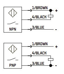
WIRING DIAGRAM
|
CONFIGURING OUTLETS
The PVB requires the use of special fittings and/or closure plugs to configure a specific outlet arrangement. All divider valves are supplied with non-configured outlets on each side and can be converted to working outlets by using fittings or plugs. Using the appropriate fitting or plug allows you to combine multiple outlets to meet higher output requirements. Closure plugs can also be used to reduce the number of working outlets. See chart below for outlet code descriptions.
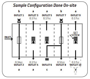
| Code | Outlet Type | Description |
|---|---|---|
| a | Working | Outlet is equipped with special tube fitting. |
| b | Closed | Lubricant ported to opposite outlet, same segment. (Internal set screw and ball1 removed, unused outlet fitted with special closure plug and clamping ring.) |
| c | Closed | Lubricant ported to adjacent segment, away from the inlet segment, same side. (Unused outlet fitted with closure plug and copper seal.)2 |
Attention: Standard or conventional tubing adapters are not appropriate.
1 Set screw (Part #74107-2644) Ball (Part #71961-4114)
2 Code “c” porting is not possible for the end segment.
HOW TO ORDER
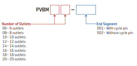
The PVB Divider Valve features a smart part number ordering system. Choose the number of outlets and the type of end segment. For example: To order a 6 outlet divider valve with a cycle pin, you would use Part #PVBM06-001.

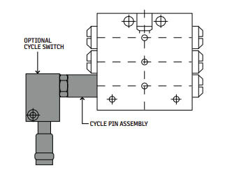 PVB Divider Valves are available with visual